Ghosting
Ghosting in the GIS is simply due to noise in the offset of the ADC's which
cause a small uncertainty in the encoded position. This only affects an
unchangable preset portion of the CDS waveband. The Look up table between
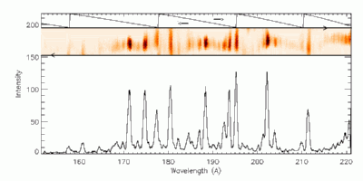
the ADC's appears as a spiral.. however it may be more easily understood
when it is unwound into wavelength space as displayed below for GSET 66 and
detector 1. Once the amount of ghosting is known it remains fairly constant
within the fluctuations of the detector high voltages.

In the example below we illustrate the raw file obtained on the 2001, August
31st at 00:26 using slit 2 at the same operating voltage as gset 62. The
left panel represents the encoded position from the ADC's of each event. The
warped nature of the spiral and the distortion is clear. Ideally each event
would occur at some position at the center of each of the spiral arms. In
this case you can see that the events jump from arm to another (ghosting) as
well as in some regions smearing across the arms. The latter smearing occurs
for theta values greater than 200. In this region the arms smear over each
other comensurately and in essence it is not position to remove the ghosts,
but it possible to know how much the region chosts by looking at the raw
files. In these regions the ghosts may be regarded as blends if they ghost
on other lines on an adjacent arm. If there are no lines it is easy to
simply relocate the ghost to its original position. This is the objective of
the next version of ghost_buster. Instead of the user using judgement with
ghosts, these will be relocated automatically.

The top right panel illustrates how the spiral unwinds into wavelength space
and the origin of 'ghosts'.The line located at around 320 A, is infact
ghosts of the Fe XVI line which is located at 335 A. The He II 304 A line is
well contained by this look up table, with no appreciable ghosting.
Similarly so for the Fe XV line at 284 A, although there is a very small
ghost of this line located to the right of the He II 304 A line.


