UCL MSSL Swift USA Swift UK Home page
Data reduction method used
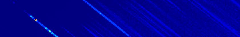
Anchor (reference) point in the first order, and other orders
In order to define quantitatively where the spectrum falls on the
detector, we choose a point in the first order at a wavelength of 260nm
for referencing the rest of the spectrum to and call that the "anchor
point" of the spectrum. Secondary anchor points are defined in the
other spectral orders at the same wavelenth (260nm) and can be
referenced to the first order anchor point or in coordinates on the
detector, usually in the detector coordinate system. The anchor point
location and the accuracy of determining the anchor point are discussed
in the context of the wavelength calibration of the UV clocked grism here .
Rotation of the spectrum
Once the anchor points of the first order spectrum is known, the
calibration also provides a predicted angle of the spectrum at the
anchor point, which is approximately the overall dispersion direction.
This angle is used as a second reference value to rotate the spectrum.
The angle phi is between 34-37 degrees, in the centre about 35.5
degrees. The transformations applied to the grism detector image (the
image
corrected for the overall distortion seen in the lenticular filters)
from pixel coordinates (x,y) to rotated coordinates (x',y') are:
x' = (x-p)*cos(180-phi) + (y-q)*sin(180-phi)
y' = - (x-p)*sin(180-phi) + (y-q)*cos(180-phi)
Where (p,q) are the coordinates of the anchor which serves as the pivot of the rotation. The coordinate system of the rotated spectrum has been chosen so that increasing wavelength is in the positive x' direction, and the origen is the anchor point.
Parametrization of the curvature of the spectra
The curvature has parametrized by adjusting a polynomial y = Σ ci xi to the spectral orders. Since this varies over the detector, this has been determined for about 30 spectra taken all over the detector. Then the polynomial coefficients for each order were fitted with a bilinear, biquadratic, or bicubic function using the first order anchor point on the detector as the argument.Determination of the width (fitted gaussian FWHM) of the spectrum
The width of the spectrum varies with order and also with wavelength, see for example the model prediction for the PSF.However, to a fairly good approximation, the width of the first order below 4500Å is about 3.1pixels, and for the second order it is 4.2 pix.
Spectral extraction in the case the orders are sufficiently separated
The algorithm for extraction a spectrum using the predicted curvature is as follows:- select a 300Å region around the predicted anchor point
- offset the pixels in the y-coordinate to correct for the curvature
- sum the counts in the x-direction
- find the peak flux location
- adjust the y-location of the anchor point to match the peak
- trace the spectrum using the predicted curvature and adjusted anchor point
- select a slit width to be the typical FWHM for first and second order.
- the curvature and slit width define the slit
- add counts in the y-direction within the slit to obtain a spectrum
- separate the first and second order based on the slit positions not overlapping
The second order spectrum, especially when the first order is saturated, will be affected by (1) the wings of the first order PSF, and (2) by the pattern caused by first order coincidence loss/centroiding.
The first effect can be corrected for by assuming a symmetry in the first order PSF. Using the trace opposite the second order with respect to the first order, an estimate of the correction can be made.
The second effect can be ameliorated by smoothing over 10-12 pixels. The result is a spectrum of comparable resolution to the first order.
In the case of a spectrum with a weak continuum, the method may fail if there are not sufficient counts near the anchor point. In that case a manual correction may be needed.
For an average spectrum, with a reasonable continuum level, the spectral extraction can use an adapted for of Keith ??? optimal extraction method by fitting gaussians to the spectral orders to define the extraction slit. In practice the method only works if (1) zeroth orders are filtered out (2) a smoothing in the dispersion direction is applied before doing the gausian fits of the spectral orders (which is of course normal to the dispersion). The advantage is a higher S/N and correcting for the slight variation along the spectrum of the width of the spectrurm. The method only works for the part of the spectrum where orders are separated, so is best done in a second pass.
Spectral extraction in the case the second and first order overlap
In this case - which occurs near the lower middle of the detector, the second order can be predicted in an iterative manner as follows:- extract the spectrum which includes the first, second, etc.
orders which overlap using a curved slit with a width of 3.2Å.
- use the uv part of the spectrum to predict the second order. For
this the relative counts in the second order relative to the first
order must be known as a function of wavelength. This is a quantity
that has been derived from calibration. Also, an aperture
correction must be applied to the second order counts, since the width
of the second order is larger.
- subtract the predicted second order counts
- iterate this once or twice. It converges fast due to the weaker second order response.
Determination of the second order sensitivity relative to the first order sensitivity
As mentioned above, to separate out the first and second order we need to know the relative sensitivities in the orders. The relative sensitivities are an instrumental function which is found by calibration.
